Session 5
Crucial advanced understanding
Please get your project of the previous session on screen (if not still opened), and in the PROJECT header, Save this project, Save project as ‘My First map-session 5’
8 TOPOLOGY
8.1 Importance of sound topology
Working with 100% sound, interlocking map data is important. It is important, but it is also difficult to achieve this.
Two reasons why it is so difficult:
- 1)A lot hinges on the skill and expertise of the operator.
- 2)The mathematics behind it all is complex. Some software packages are not so good in handling this.
Two examples:
- 1)Gaps in between two abutting polygons mean we could be short-changing ourselves when selling Hectares of land or applying for grants.
- 2)Overlaps in our polygon means we could be overcharging tenants or are selling more land than we actually have in hand.
Two formulae
- 1)It is important to work with sound topology, because the map data represents ‘value on the ground’.
Einstein cracked the code of the universe with his formula: E=mc2
We can now try to remember this sobering truth:
Ha=M
Which stands of course for:
Hectares = Money
Try to remember that when making a map.
That is why good map data, good mapping software and knowing how to go about it is important.
- 2)And closely related is the following formula:
S=M
Which stands for:
Scale = Money
When drawing at a small scale (like the current map 1:30,000) the map can be ready in minutes, yet the accuracy may not be all that good. Draw the same shapes at 1:1,250 scale and it will take you hours, yet the accuracy is optimal. Time = Money and Accuracy (Ha) = Money.
In sum: always draw at an appropriate scale
Which mapping scale?
Now that we have memorised these formulae, the next obvious question is:
“What is an appropriate scale to draw in?!”
A golden rule of thumb to remember is this:
Always draw at least at half the presentation scale.
And that means that when you want to print the map at 1:1,000 scale we shall map at 1:500 scale. Or when the map will be presented in a PDF at 1:25,000 scale, we should be drawing at least at 1:12,500.
Practice has it that when we draw at half the presentation scale we will strike a good general balance between formula 1 (Ha=Money) which is the accuracy with which we draw our map objects, and formula 2 (Scale = Money), the time we spend on the map.
In the paper world, all this was not an issue, we just drew as accurately as possible in the presentation scale. But with digital mapping we will be zooming in and out and it is difficult not to get carried away with spending too much time on detail when the final map will not or cannot even show that detail!
But remember: it is a ‘rule of thumb’. In practice, personally, we tend to zoom in a bit more, here and there. Some advocate mapping at 1/4 of the presentation scale, but that seems a bit over the top to us.
8.2 Topology Basics
So, to know about ‘topology’ is absolutely key in digital map making. In the last session, with the last line we moved, we saw that the ‘topology’ of these two polygons was ‘sound’.
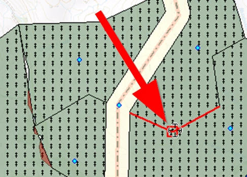
They are ‘interlocking’ – with no gaps or overlaps. When we change one boundary, both polygons will take on a different shape and the all-important Ha will be updated properly and automatically in both shapes.
Thus, a definition of topology can be:
the way in which constituent parts are interrelated or arranged.
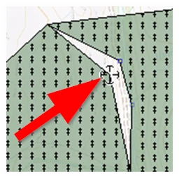
In the example image below, we can see that there are gaps and overlaps - errors in the topology. Inevitably we end up with a wrong Hectarage. When we change the location of a corner (in our scenario), the gap will increase or decrease, depending which way we move that one junction/vertex.
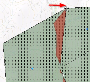
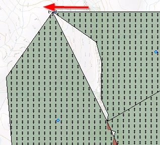
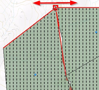
When we place the mouse (with the EDIT tool active) in between two vertices (see image below), we see that the small red square appears, and when we now click, hold and drag, we are inserting a new vertex which we can drag onto the other boundary, partly amending the gap:
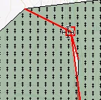
And so, step-by-step we can amend the errors in the topology and get the Hectarage spot on. We will do the next section:
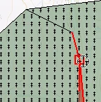
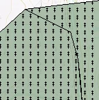
If you are following along, nearly exactly what we are doing, please press the F1 key now before we demonstrate the next feature. We will demonstrate the next things, and also emphasise how to make use of saving your project at specific moments.
Placing an object in ‘Edit mode’
Sometimes these boundaries are in such a twist it is difficult to see how to untangle them. In such cases it might be opportune to click twice in one polygon (whilst the EDIT tool is active). This will put that one polygon into ‘edit mode’.
This means we can now very clearly see the vertices and line segments constituting this one polygon. But now, when we edit the geometry, we are only dealing with this one polygon, the adjacent polygon remains untouched.
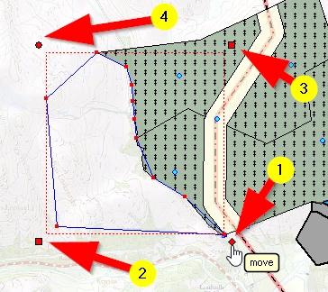
In the image below we can see one polygon is in edit mode. We can move the cursor over a red dot and click, hold and drag it into a new position. This is all very useful for untangling awkward mishaps. But to put things in edit mode can also cause other troubles, so don’t be too quick in opting for this. Here is an example why you must be careful using edit mode:
With the object in edit mode, we can see on the corners of the red dotted extent line, different symbols.
(1) Hovering our mouse over the diamond, bottom right we can click, hold and move the entire polygon to a new location.
(2 & 3) offer us an option to ‘stretch’ the object (square) and
(4) offers us an option to rotate the object (circle).
Below, we have moved the object, rotated it and stretched it in two directions.
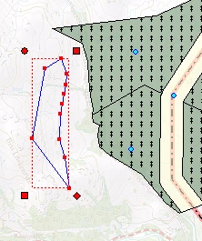
Usually, when making maps we do not wish to make use of these options at all. A map maker likes to draw things as they are. Yet these options are quite useful to have, particularly when designing things.
Undo and redo
But as we can see, we have well and truly muddled up our newly added compartment. We could try the ‘undo’ button but there are limits to what MM5 will undo for us.
It is for this reason that we asked you to save our project. Assuming we did that, we can now close our project - without saving anything - and open it up again. Because MM5 will have also saved the live layer as we did the F1 save, all should come back exactly as it was.
(1) Click on the PROJECT header
(2) Click on Open an existing project, and MM5 will list the recently opened project.
Select ‘My first map-Session 5.geo’.
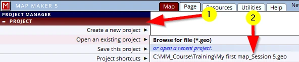
The project should open again, showing the new compartment – still with its gaps and overlaps.
We can now amend this with the EDIT tool one vertex at a time. This is of course time-consuming and, for that reason, MM5 has got a very useful tool - the SNAP tool...
8.3 The SNAP tool
Now that we know the importance of sound topology we realise that it is crucial to get it right. We have seen that we can use the EDIT tool to amend errors step-by-step. Here is a faster and usually a better way of amending such mistakes:
(1) Activate the SNAP tool
(2) Click once in the polygon and often this will close the gaps.
In case the gap or gaps are too big for the mathematics involved to resolve it automatically please click and hold in the polygon which has the wrong boundary, then...
(3) ...move the cursor into the polygon with the correct boundary and let go of the mouse button:
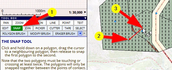
The first polygon will have snapped onto the boundaries of the second polygon.
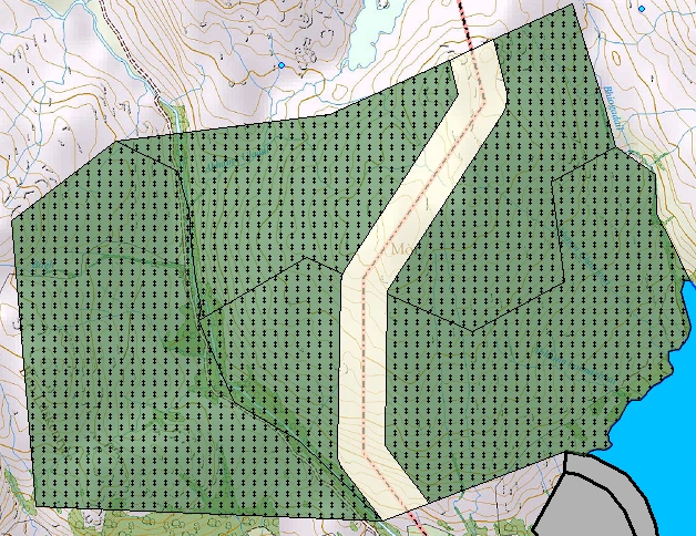
MM5 offers some excellent tools to automatically amend errors in topology which can be found in the menus:
Utilities, VECTOR, polygon topology
However, that is too much for this beginner’s book to deal with!
8.4 Snap options
OK, we get it. Creating maps with sound topology is important and the SNAP tool is a great tool to amend minor errors. It would be good however to avoid gaps and overlaps in the first place.
Layer snap settings
We saw that Map Maker is in fact already helping us to draw good interlocking polygons. We noticed that as we drew a line over an existing polygon or line, the interface changes subtly, to inform us that the cursor was in range of another, existing line and that it would snap to another existing vertex in range. Those existing lines and vertices are ‘magnetic’ - as it were, they ‘pulled’ the new line to themselves, that is ‘snapping’.
99.9% of the time we do want to snap to other map objects in other layers, sometimes we don’t. There is a setting to turn this off:
(1) Select the layer you do not want to snap to
(2) Click on the little blue arrow to open more options
(3) un-check the option: layer can be snapped to
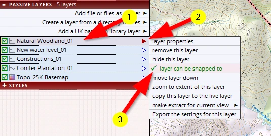
When we do not want to snap to an object in the live layer we simply have to zoom in, so that the cursor remains out of the ‘magnetic’ range of other objects in that layer.
Object drawing snap settings
There are a number of other ‘snap options’ which deal with how individual objects to be drawn respond. These options can be found here:
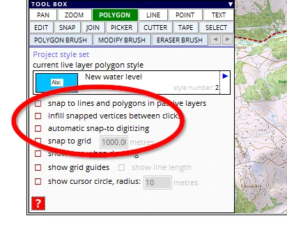
These options change slightly when it comes to drawing the different objects: polygons, lines or points.
This is what these different options do:
- 1)snap to lines and polygons in passive layers: ‘does what it says on the tin’.
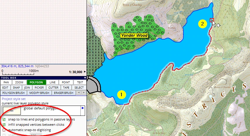
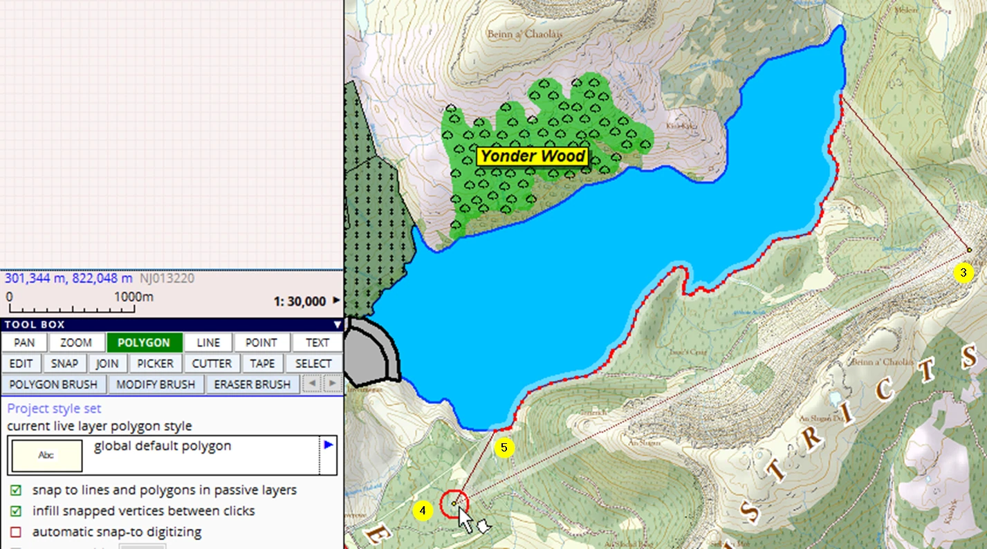
- 2)Infill snapped vertices between clicks: this is a very efficient setting when we need to follow a long complex existing line. Click where you want to start the new line to follow an existing line, click once more further along this line and the software automatically traces the existing line in between these two points.
Please look at the example below: it would take considerable time to trace the lake shore once again – with the chance that we may skip a few red dots (vertices). With this tool we can draw a new woodland in 5 clicks flat! Sound topology, no overlaps, no gaps.
Note: One should bear in mind that the software always follows the shortest route between click 1 and 2, and that at ‘T-junctions’ it often would not know which way to go.
- 1)automatic snap-to digitizing: this option will automatically draw a ‘snapped’ line wherever the mouse is hovered over existing objects. This too is a very fast way of drawing, but demands a good mouse control otherwise it snaps all over the place.
- 2)snap to grid: once activated we can type in a desired grid spacing. This is a very useful option in map design or even ‘constructing’ things (architectural drawing work!).
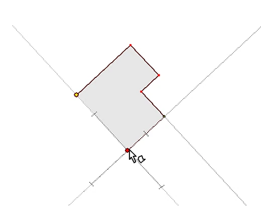
- 3)show grid guides; this too makes use of ‘snap’ functionality. It is an aid to draw perpendicular lines. Try it. It shows a guide line when moving the mouse. When moving the mouse close to this line, the next click given will snap to that guide line, thus creating rectangle lines and shapes.
Note the mid-point indicator and note how the cursor does changes shape and colour when the next point is lined up with a previous entry.
An extraordinary handy tool to map out buildings (or design a e.g. a barn)!
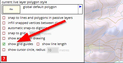
The other options do what they say they will do: show area when drawing, show line lengths and show cursor circle radius. These are all aids which are helpful when setting out and designing features.
Please clear the live layer if you have tried all sorts.
9 LABELS
9.1 Show labels, types & options
We have seen we can give each map object a CAPTION, a name (in the new object menu or by accessing this menu again with the edit tool):
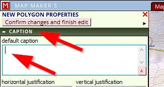
Each map object can be adjusted so that this name, this caption can be shown on screen. However, this is intelligent vector data, so we have more relevant information which might be useful to show on the map. For example, the location in the national grid (X,Y coordinates or UK OS ref) or the area involved, or any other ‘Attribute data’.
When we show such information on the map, it is referred to in a generic term called ‘Label’.
To see this label functionality in action, please select the layer ‘Natural Woodland_01’ in the PASSIVE LAYERS header.
(1) Click on the little blue arrow (which then turns red)
(2) Select the option layer properties
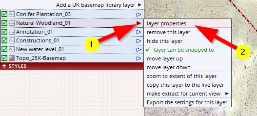
A new menu will open:
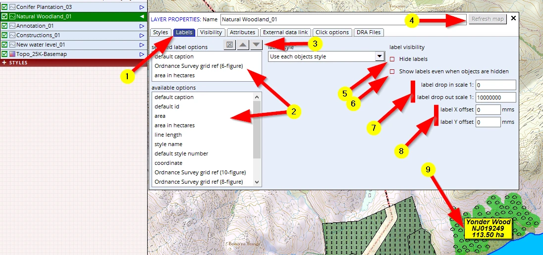
(1) Select the Labels tab
(2) Click on a specific label (or more than one) in the left list and it will appear in the right window.
Scroll down the list and see for example the option ‘OS Field number’ – UK Farmers and Land Agents will like this option. Any ‘attribute’ data (see later) can also be shown as a label once defined.
(3) The sequence in which the label options appear can be changed here (or delete an entry using the red x)
(4) Use the ‘Refresh map’ button to see the result on screen
(5) We can also hide all labels
(6) This is a setting which is useful in more complex GIS/map making work
(7) With these settings we can adjust a specific scale range in which the labels will be visible
(8) And with these settings we can move all labels in this one layer, globally, with a particular offset, as opposed to moving a label of one specific map object
(9) With our selected options we get this result.
And remember: the yellow panel was defined in the style set.
F1 to save your project.
The following three things are important to understand and remember:
- 1.Label setting can be found in the layer property menu, which is the same menu in a live as well as passive layer. When we adjust these settings in the live layer header, they remain active until we change it again in these live layer settings.
So whatever else we will be drawing in the live layer (points, for example, or lines) this particular label will show. When we draw a polygon and adjust it to show an area, it will show. But when we then create a new layer with lines and point there is no area involved so it might look odd or wrong. We can of course decide at any time to show no label at all.
- 2.Once a live layer is saved it becomes a passive layer, and that passive layer will retain the label settings which were used in the live layer when we drew these objects in it.
- 3.Regardless of what live layer label settings are active, when we copy a passive layer into the live layer to work on it again, the label settings of this passive layer will be carried over into the live layer settings.
Although these are important things to remember, in practice you might not even be aware of this behaviour because it flows quite naturally.
9.2 Split circle label (forestry)
Foresters have a specific label requirement showing compartment numbers and Ha. This is how it is done:
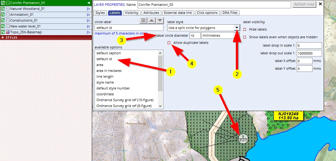
Please select the layer ‘Conifer Plantation_03’.
Adjust the following label settings:
(1) Select the default id as a label
(2) for the label style please select Use a split circle for polygons
(3) We can change the size of the circle here
(4) Some times Unique IDs (or in forestry terms, ‘Compartment Numbers’) are not so unique after all, we have this options to allow for such oddities.
(5) The result is this label where the ID is shown in the top half and the area of this polygon is shown in the bottom half of the circle
Note: Because we have not changed any IDs in the new compartments, they all retained the ID of the very first outline we drew. Woodland compartments always should have a unique ID (hence the name ‘ID’), if for an odd reason there are other polygons with the same ID.
F1 to save this project.
And as a side note but equally handy: using similar ‘scale dependent’ behaviour settings in the Visibility header, we can also hide and unhide an entire layer at particular scales.
9.3 Editing labels
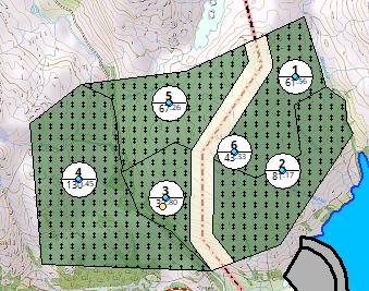
We had drawn this woodland with one polygon and assigned an ID to this one polygon: ‘1’. We then used the cutter tool to subdivide this into smaller polygons. And so all of them retained that same ID. This is of course an impossibility- they should all have a unique ID, a unique compartment number.
Any physical changes to map objects (like changing or typing up a label or ID) can only be done in the live layer. This layer is a so-called ‘passive layer’ – it is a saved and existing drawing. In other words, we need to copy this layer into the live layer to be able to shift its location or edit its content:
Please select the Conifer Plantation_03 layer
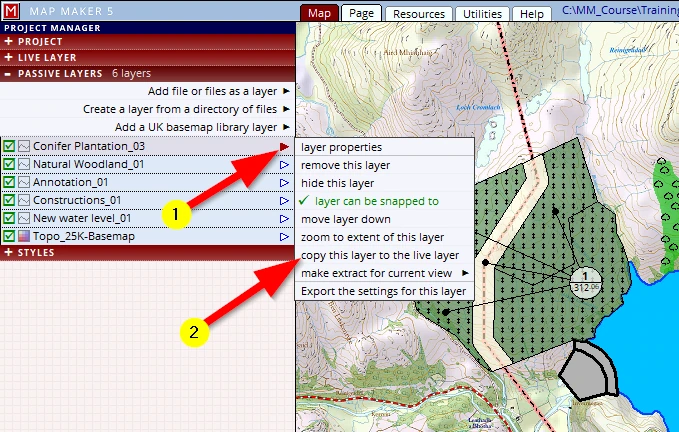
(1) Click on the blue arrow of the Conifer Plantation layer (which then becomes red) and a menu opens
(2) Click on copy this layer to the live layer
Observe that:
- 1-this layer disappears from the passive layer list and from now on all settings to be adjusted or used can be found in the LIVE LAYER header.
- 2-we now see the little blue dot in the centre of the polygon indicating it is ‘live’, ready to make physical changes or additions to it.
- 3-by default labels appear in the mathematical centre of a map object.
Now that it is in the live layer we can amend (or add to) this layer.
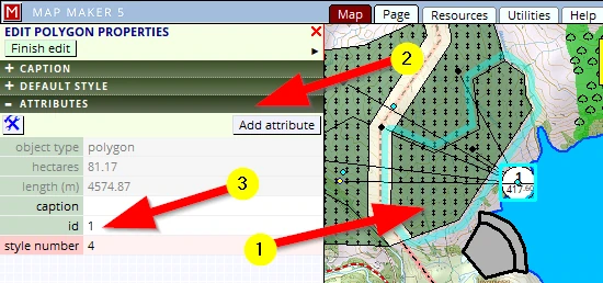
Please activate the EDIT tool and
(1) Click once in this polygon (and observe it will now have a blue outline). Note that the interface on the left changes and shows headers in green,
(2) Open the ATTRIBUTE header
(3) Change the id to: ‘2’ then confirm changes to close the menu down
Please assign an ID to the others as well
Note that we can also change the ‘Caption’ and the ‘style number’ in this menu.
Please leave this live layer on screen.
9.4 Label positions
Now we hear some mumblings from the astute student: “did you not just say in a previous section that by default all labels of new polygons appear in the centre of that new polygon’...? But looking at compartment 6 this is not the case...?” Well yes, we did say that but so it does!
Look. Here is a polygon with the label neatly in the mathematical centre of this shape:
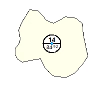
When we put it in ‘Edit mode’ (click twice on the shape with the EDIT tool) we can see the clicks that we gave (red dots), the connecting line in blue and we can see that MM5 drew a rectangle around the object defining its minimum and maximum extent (red dashed line)
.
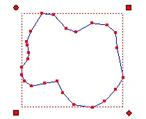
To establish the ‘mathematical centre’ of an object one can draw the diagonals, and at the intersection of these diagonals (the centre) the label is placed.
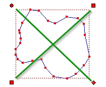
And that means that when we are dealing with a sort of ‘banana’ shape, that mathematical centre of the max extent rectangle is outside of the polygon.
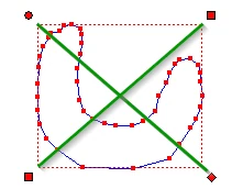
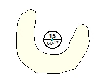
This is the reason why it can seem your labels are all over the place. MM5 has tools to put the label inside the banana automatically (Utilities, Vector, Amend labels).
Dealing with the locations of labels is one of the last things we do when making a map. This is because labels will shift whilst editing the shape of polygons. But also (and this depends on style settings), as you zoom in or out, those labels will become bigger or smaller.
Zooming out, the labels remain the same size, but the overall appearance is that they look to be way too big and soon will start overlapping each other if we were to zoom out even further.
This is because, as it is, the size of the labels is defined as ‘millimetres on paper’.
9.5 Moving Labels
So, these forestry type ‘split circle’ labels are now in the middle of the compartments and we want to move them because it is good practice that the label is placed outside of the compartment (because it potentially can obscure relevant information in that stand).
We will first change the scale to 1:30,000
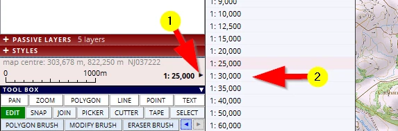
We have this layer still in the live layer. If it was a ‘passive layer’ we could not edit any of it.
(1) Activate the EDIT tool
(2) Move your mouse over the caption and observe that things change a bit:
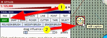
Click, hold and drag the label to a new location:
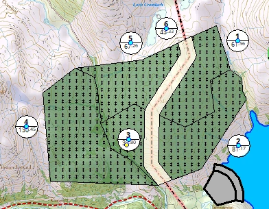
We think we like these changes and want to save it:
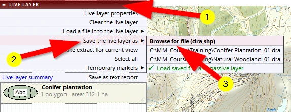
(1) Click on the LIVE LAYER header
(2) Click on Save the live layer as
(3) Browse to the Training folder and give it its new name: ‘Conifer plantation_04’ (version number 4!)
Follow it up with a F1 to save your project.
9.6 Label sizes (mm or m on the ground)
As mentioned, the position of labels is usually done in one of the last stages of map making because the size and location hinge on the final presentation scale. The font size can be adjusted in the style editor (F2) here:
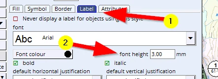
These sizes are by default defined as ‘millimetre on paper’. However, there is a tick box option which we can apply which changes the definition of sizes to ‘metres on the ground’. It can be found in the style editor in the Attributes header of each style entry:
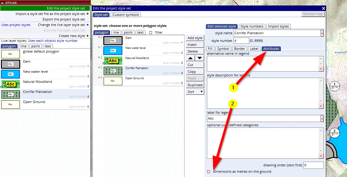
We can use this setting to fine tune the appearance on the map. For maximum legibility we want to place text in such a way that, for the most part, it does not overlap or obscure other map details.
Millimetre on paper
When the style is defined in mm on paper, when we zoom in (to find the best possible spot) we still cannot see the exact results of repositioning these labels. Because, as we zoom in, the Base-map will become larger and larger but the text itself remains exactly the amount of mm (on paper) which we specified in the style file.
This option is usually most suitable for digital presentations or management set ups, where the map is only viewed and interrogated on screen.
Metres on the ground
When on the other hand we define the text sizes in ‘meters on the ground’, we can zoom in and both the Base-map and the texts become larger so we can move the labels into a perfect (clear) spot.
This option is mostly used in map productions where the output is a paper map (or PDF/raster version), because with this option we can zoom in and move labels with ultimate precision.
It is an art to place text/labels in such a way that it touches as few possible lines or map objects and yet that it is clear to the reader where the label relates to.
Regardless of size definitions, just remember this one thing:
whilst working on a project like this, shapes will change, locations of map objects are not fixed, and the sequence of layers is in flux. It is therefore best to only adjust the location of the labels as the last thing, just before printing. And we adjust them to the scale we want to print at.
9.7 Label arrows
Compartment 3 is surrounded by other polygons, so when we move the label, out the map reader would potentially not know to which polygon the label relates to. MM5 offers an option to create an arrow. It works like this:
Copy the Conifer Plantation_04 layer back into the live layer.
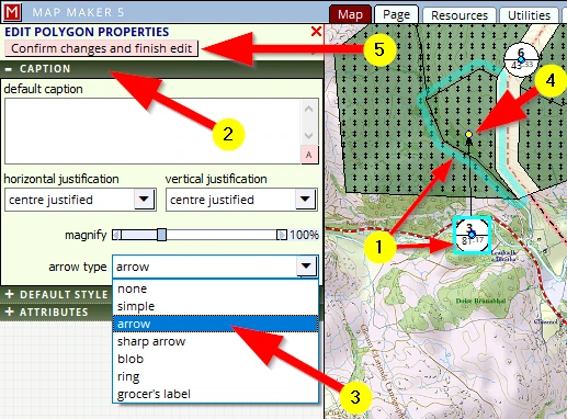
Activate the EDIT tool and click on the polygon.
(1) Note how the polygon is highlighted in blue. The label also is marked, which is very useful when you are dealing with tiny polygons in amongst many other polygons and labels (like in a complex and dense forestry management plan)
(2) Click on the CAPTION header
(3) Select an arrow type you like – we have selected arrow
(4) Note the start point of the arrow. With the EDIT tool still active on this polygon we can now move where the arrow is pointing to (Click, hold & drag).
(5) Once done: Confirm changes and finish edit
The ‘open ground’ label (CMPT 6) also needs to be moved out with an arrow.
Save the live layer with increased version number, save your project.