Session 6
Custom symbols
We want to warn folk who use the map that the power station with all the high voltage involved is actually a dangerous place to be. We want to insert a symbol on the map with the usual lightning bolt ( ).
10.1 Creating a custom symbol
To place a symbol on the map we need of course first to define a style in the style set. Here we go:
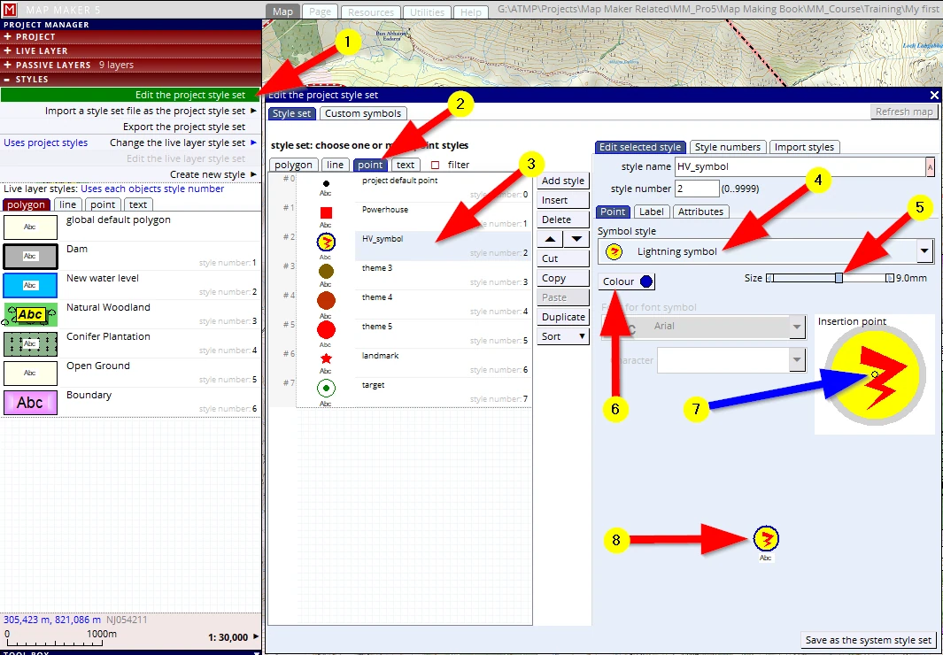
(1) Click on the STYLE header
(2) Edit project style
(3) point tab
(4) select an existing style which we don’t use (e.g. ‘theme 2’)
(5) Change the name to e.g. High Voltage symbol: ‘HV_symbol’
(6) Scroll down the list of the default MM5 symbols to find a suitable symbol. We will discover there is no such specific symbol pre-cooked for us. Fortunately, at the very bottom of this list we can see an option called:
font character. This is good! Because in Windows there are several fonts which have all sorts of weird and wonderful symbols.
(7) Change the colour to red
(8) Because we opted to use a font character, we must select a specific font. Windows has the so-called ‘Wingdings’ fonts on offer; let’s select one of those.
(9) In the Character selector we can scroll down the characters in this font to find a suitable symbol.
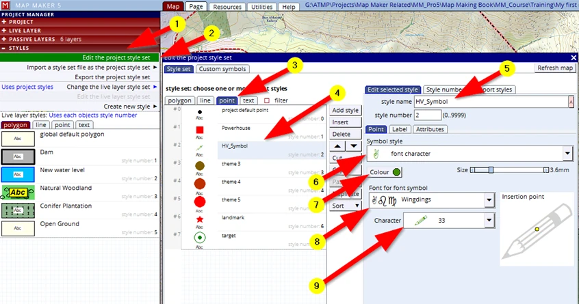
The symbol (lightning bolt) we have in mind is not in this font set. We could change the font and start looking in others. That takes time. Fortunately it is not a big deal to design our own symbol in MM5.
This is how it is done. Leave the style editor open.
With the opened style editor:
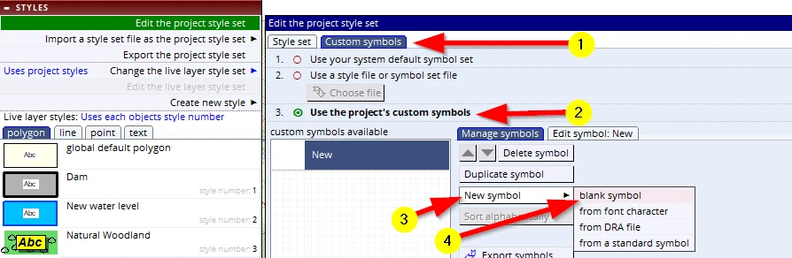
(1) Click on the CUSTOM SYMBOLS tab
(2) Click on the this option: Use the project’s custom symbols
(3) Click on the New symbol button
(4) Chose blank symbol (and note at his point all the other options you can also apply!)
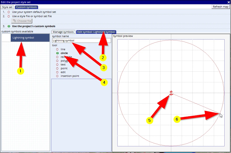
(1) Select the New symbol
(2) click on the tab Edit symbol: New
(3) rename the symbol (e.g. ‘Lightning symbol’) – and note how the tabs take on this name
(4) Activate the circle tool
(5) Click and hold in the centre of the Symbol preview screen and...
(6) ...drag the mouse and see a circle appear.
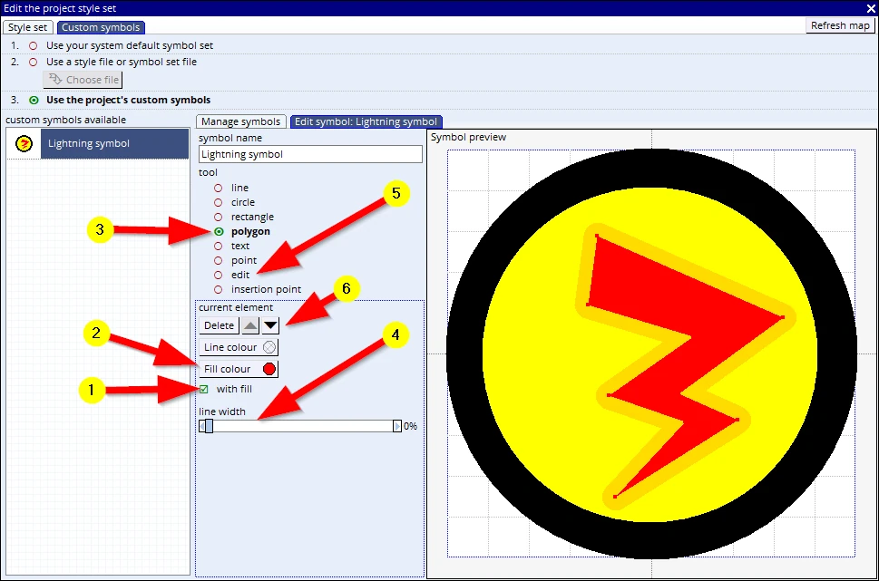
As soon as we let go of the mouse button the interface changes:
(1) Ensure the tickbox ‘with fill’ is checked
(2) Change the Fill colour to yellow (leave the line colour untouched: i.e. unspecified) and adjust the line width (4) to about 15%
You will now have a thick black circle with yellow fill.
(3) Activate the polygon tool, draw a lightning bolt and right-mouse click once done, the interface will change again- give it a red fill
(4) Set the line width to 0%
(5) After a component is drawn it can be edited:
- -single click, hold & drag to move an object
- -single click in the object to put it in ‘edit mode’
- -single click on a vertex to delete it
- -click, hold and drag to insert a new vertex or move an existing one.
(6) the sequence of objects (one over the other) can be change or can be deleted.
We don’t want to do that again- F1 to save your project!
Close this menu down on the white cross (x) top right above ‘Refresh map’.
Now that we have designed our symbol, we can go back into the style editor and select our designated style (1-3)
(4) Select our new symbol.
(5) Change its size to 9mm
(6) Change the colour to dark blue.
(7) Note the ‘insertion point. In this case we shall leave it as is, but for some symbols (e.g. Prominent tree, Mast) we may like to change this placement point.
(8) Observe the following:
- in this little preview we can see how the symbol will look on the map.
- we designed the symbol as a yellow circle with thick black rim. However, we now see it has a blue rim. And when we change the symbol Colour (7) to dark red we see it will have a red rim!
This is because as we designed the rim line, we did not assign any colour. It showed black, but this means that this unspecified colour will take on the colour as indicated in the symbol colour setting.
This is particularly handy, for we can now design either:
A full colour symbol where each object has a predefined colour,
Or
We design an entire symbol in an ‘unspecified’ colour (which shows black in the symbol editor) but that means we can change the colour in the usual Style editor menu.
(In this scenario, for demonstration purposes, we did a combination).
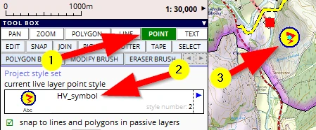
We can now place this symbol on the map:
(1) Activate the POINT tool
(2) Select which symbol we want to draw
(3) Give one click in the map on the location we want our ‘High Voltage’ warning the symbol to show
Note: This sequence of assigning a style fill is different to what we have done before.
Here we basically set a ‘default’ style to this object. As soon as we activate this object, this is the pen, the style which MM will use.
In previous scenarios we mentioned but did not use this option, we simply drew an object and then in the style header of that object we assigned a style number after we drew it.
This option is particularly handy in the following situations:
- Use this ‘Before drawing’ option when you know you have got a lot of objects to draw with the same style.
- Use the ‘After drawing’ option if it is a one-off, or you realised it should be a different style after you have drawn it.
We need to save this live layer and give it a name and, of course, put it in our training folder:
C:\MM_Course\Training\ Symbols_01
F1 to save the project.
10.2 Polygon symbol fill
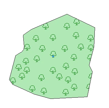
A custom symbol like the one we created can also be used in any fill pattern. We could for example design our own tree symbol (in an ‘unspecified colour’) and then put it into a fill pattern in dark green like so:
We shall not do a pattern fill now, but it can be found in the Style editor here:
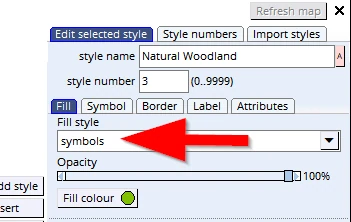
In the Style editor, select the style to change, select the option symbols in the Fill tab, then in the Symbol tabs, scroll down the list of available symbols, and at the bottom you will find your custom tree symbol. After that adjust the Size and Spacing etc.
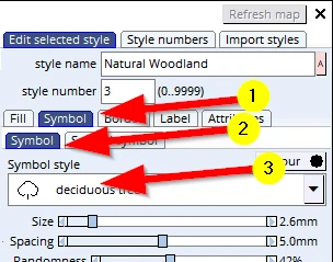
10.3 Line effects: symbol line
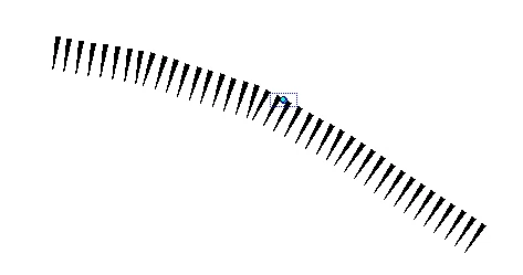
Any custom symbol can also be applied to a line. See right, where one custom symbol, a pointy triangle is repeated on a line, where the actual line style is set to ‘none’.
Let’s create this symbol line, as we can use it in our map!
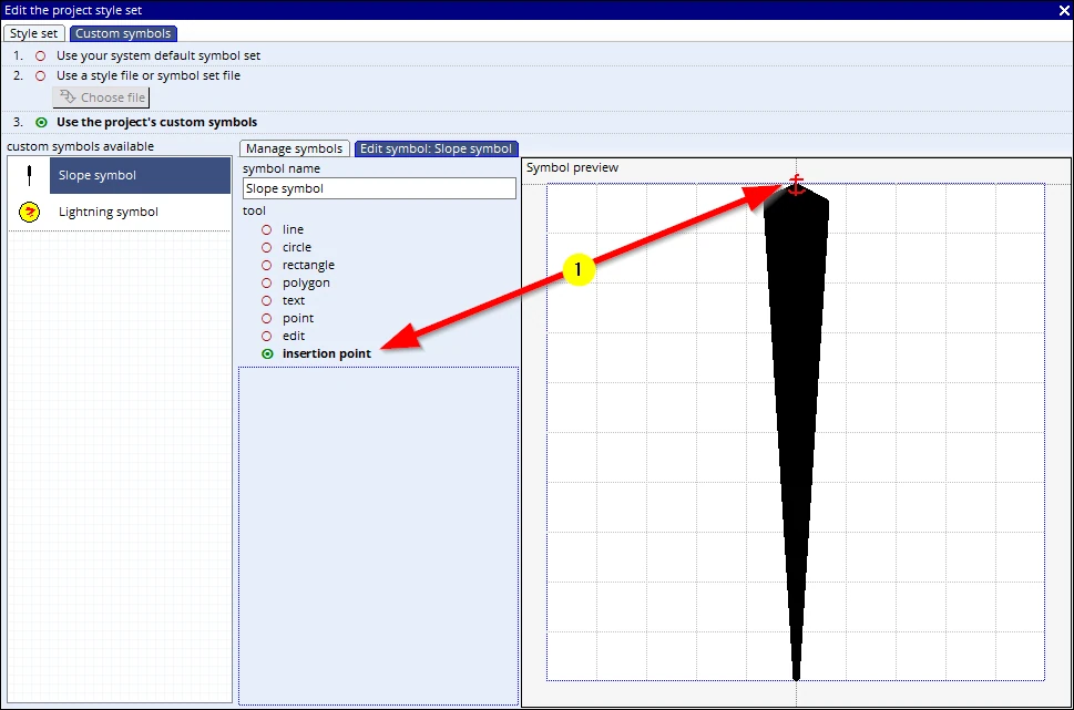
Create a thin triangular symbol with the polygon tool in the Edit custom symbol menu but now also activate the ‘insertion point’ (1) and click in the top of that symbol. Name the symbol ‘Slope’ and leave its colour untouched which means its ‘colour’ at this stage it is un-specified.
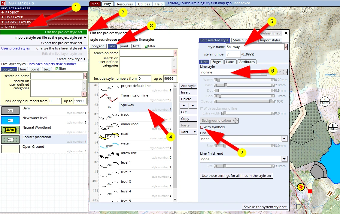
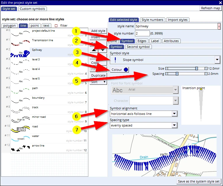
(1-5) Go to the Style editor, select a line which you have not used (or create a new one) and name it ‘Spillway’.
(6) Change the Line style to no line
(7) Tick the box With symbols (note that a new ‘Symbol’ tab appears in amongst the others)
With this menu still open, try the following:
(1) Click on that Symbol tab
(2) The next row of tabs opens on the Symbol tab as well. Note: we can even add a second symbol if we want!
(3) Chose our newly created ‘Slope’ symbol
(4) Change the colour to dark blue
(5) Adjust the size and spacing (we used size: 12mm and spacing: 2mm)
(6) Change the Symbol alignment to horizontal axis follows line
(7) Note that we can also change spacing to other options (applicable in our next example)!
Close this menu down, save your project (F1)
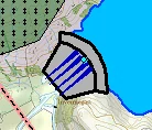
Draw a straight line at the top of the Dam. It should look something
like this (at 1:30,000 scale):
We need to save this layer.
Although it is a ‘line’, we would class this as a ‘symbol’.
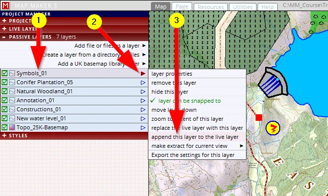
We already have got a layer which deals with symbols, the High Voltage warning symbol. That layer is called ‘Symbols_01’ and can be seen in the passive layer list. Ideally this ‘symbol’ should be part of the Symbols layer.
This is a typical mistake scenario: we forgot to copy this layer into the live layer first, before drawing this new symbol line in it... and thus MM will have created a new layer instead of putting it in the ‘Symbol_01’ layer.
MM5 accommodates...
(1) Select the layer it should have gone into (Symbols_01)
(2) Click on the little blue arrow for the ‘immediate actions’ menu - the arrow becomes red
(3) Select the option append this layer to the live layer
We can now go to the LIVE LAYER header and select the option Save the live layer as, and give it the same name (with increased version number): Symbols_02
Save project F1
Now that we have learned how to apply symbols to lines, we can also apply this to our transmission line.
A real world transmission line is not only the line, it also has pylons. Let’s add those!
Open the style editor again:
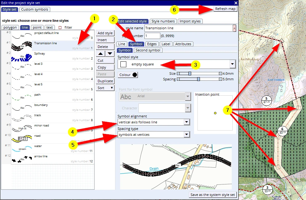
(1) Select the ‘Transmission line’, and in that menu tick the box With symbols again
(2) Go to the Symbol tab
(3) Select the symbol: empty square
(4) Now select the following option: Symbol alignment: vertical axis follows line
(5) and in the option Spacing type select symbols at vertices.
(6) Refresh the screen and…
(7) Observe that we now have pylons at every turn in the transmission line
10.4 Line effects: edge band graded
We are now almost ready. The only thing missing is the boundary of the project site.
We need to define a style which will give the boundary some colour. We tend to think of a boundary as a line, a boundary line. But a boundary encompasses a site, it defines an area, and thus we need to think of defining a polygon style. Here is what we can do:
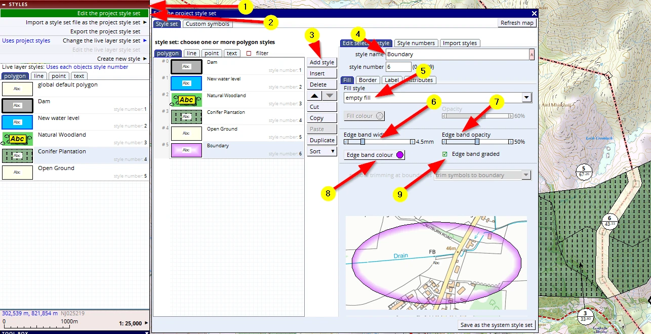
(1-4) Open the style editor, Click on the polygon tab, Add a new style, Name the new style ‘Boundary’
(5) Fill type: ‘empty fill’
(6) Edge band width: 4.5 mm
(7) Edge band opacity: 50%
(8) Edge band colour: choose something purple
(9) tick the box: Edge band graded
And whilst we are in this menu, we can also adjust the font, size and panel colour for the label:
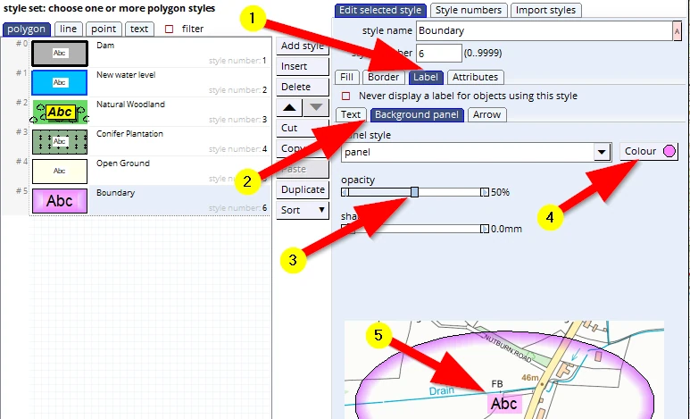
Note: As a label panel colour, we opted for the same purple as the boundary line, suggesting the two are related.
F1 to save these changes by saving your project.
We can now draw the project boundary and assign the appropriate style to it.
Please activate the polygon tool and digitise the boundary fairly similar to that as shown below:
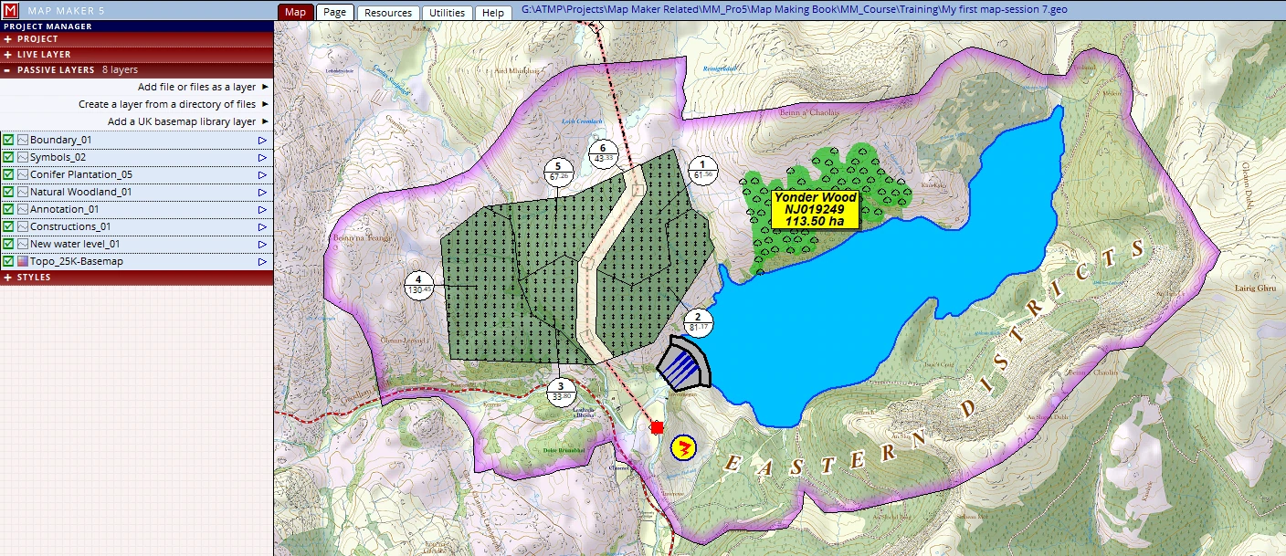
Save this new live layer in the Training folder and give it the name: Boundary_01.
F1 to save the project.
10.5 Line effects: roads and tracks
We have built the dam and powerhouse, but this could not have happened without a new road which we will now draw. To do so we must first make sure we have a style available.
We need to open the Project style set:
Click on the STYLE header, Edit the project style set, line tab.
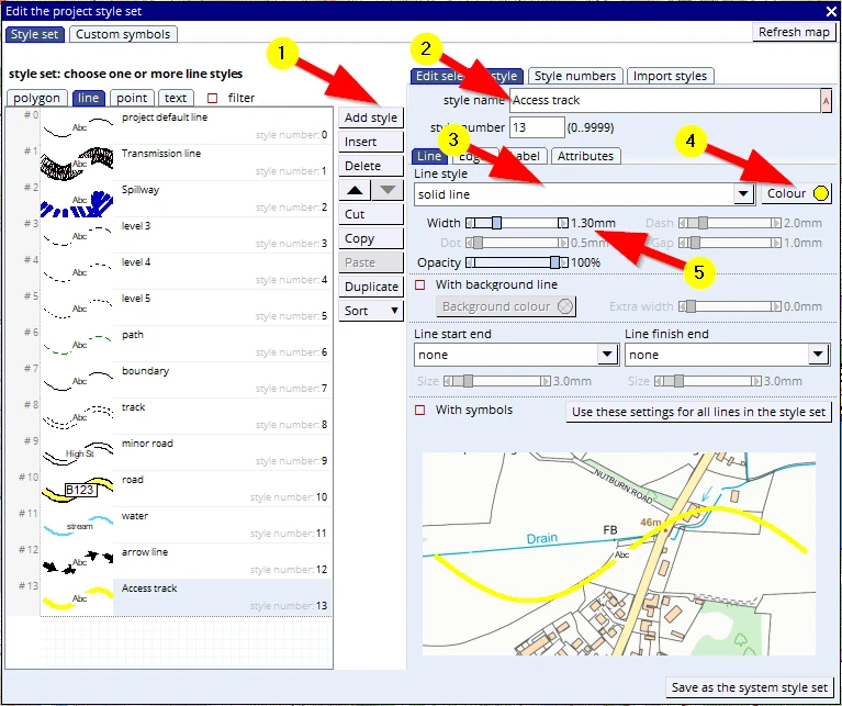
We see there are already track and road styles but we would like to change things in it.
Note: Unlike the other predefined styles, the properties of these road styles are (so-called) ‘hard coded’ into the software which in practical terms means we cannot change them.
And so we will create a new style. We have done this before, so it is no problem to create a new style:
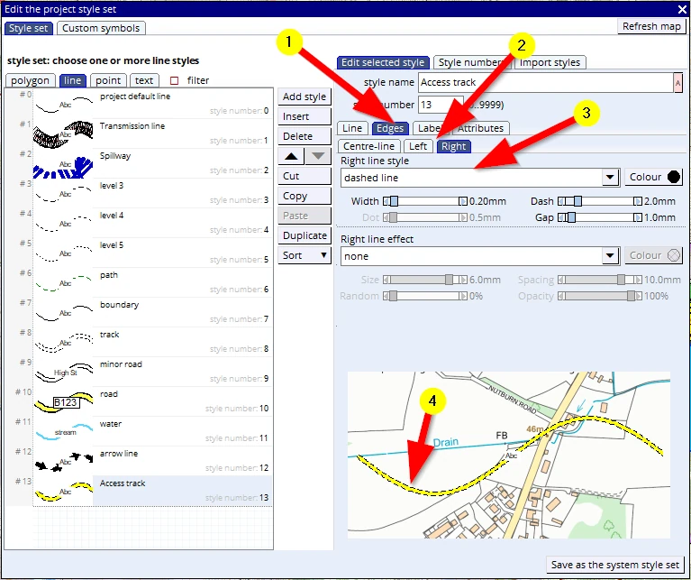
(1-5) Create a new line, call it ‘Access track’, make it a solid yellow line and 1.3mm in width:
Note: One can also type in a specific value by clicking on the displayed value next to the slider bar.
Note: when ‘adding’ a style, it appears at the bottom of the list, unlike ‘Insert’ where it will be placed below a selected style.
Then:
(1) click on the tab Edges tab
(2) click on the tab Left
(3) please change the Left line style to dashed line and do the same in the Right tab.
(4) the resultant line looks like this.
F1 to save this new style.
We can draw the new road using the LINE tool and when done we will tell MM5, by using a right mouse click, that can stop drawing. The interface changes and we need to assign the right style to it and click on the button:
Confirm new line.
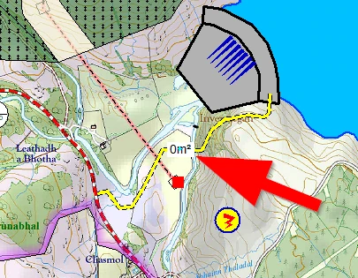
Note:
- that we have drawn the track crossing the transmission line and right up to the top of the dam.
- We have been playing with our label settings and currently it is showing the area of the track. However, it is a line (although it shows a specific width). But this is it: Live layer labels can be useful, but often, if not most of the time, they just get in the way of what we need to see in the Base-map. As mentioned before, often we just turn them off here:
(1) Hide labels
or alternatively,
(2) delete the selected options
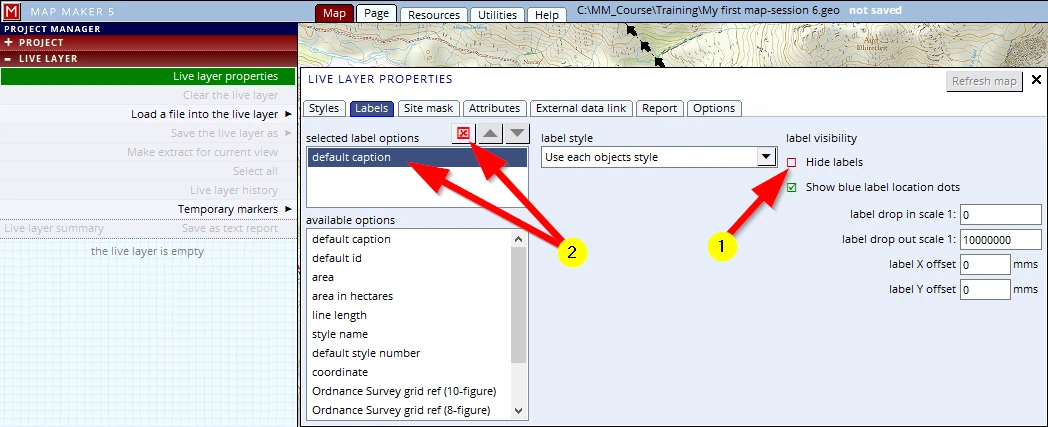
This setting is ‘carried over’ to the passive layer label once this live layer is saved.
We need to save the new layer and will save it in our training folder and give it its new name:
C:\MM_Course\Training\Roads_01
We follow this up with a ‘Save Project’ (F1)